sapstro Posted January 17, 2010 Share Posted January 17, 2010 Before buying ADboard kit, you must confirm that ADboard kit match to your LCD pannel. In my case, two LCD signal cables were simply connected line to line by soldering. I used name tag for exact connection of line. Wow, thank you for sharing this gorgeous project. Really nice work. I always wanted to use my old imac G4 as a standalone monitor. Can you tell me how you knew about the pin configuration of the video cable coming out of the display ? I mean, how did you get out which cable you have to connect to which pin on your AD board ? It would be very nice of you if you could share this information ! Thanks a lot. sapstro Link to comment Share on other sites More sharing options...
ballin805 Posted January 17, 2010 Share Posted January 17, 2010 Wow, thank you for sharing this gorgeous project. Really nice work.I always wanted to use my old imac G4 as a standalone monitor. Can you tell me how you knew about the pin configuration of the video cable coming out of the display ? I mean, how did you get out which cable you have to connect to which pin on your AD board ? It would be very nice of you if you could share this information ! Thanks a lot. sapstro if your really interested then here you go i was going to post this up but i haven't got around to it till just now this should work for the 700mhz,800mhz, and 1ghz 15" imac g4 LCD it should also work on the 17" inch model i guess the only way to find out is to take your LCD out and check the cable coloring by carefully peeling the tape on the connector. http://hidekyan.cocolog-nifty.com/blog/2009/07/index.html Link to comment Share on other sites More sharing options...
Frogburn959 Posted January 21, 2010 Share Posted January 21, 2010 It is my understanding that DVI is a digital signal and VGA is an analog signal, then cable used in the iMac g4 is a TMDS which would be the equivalent of a DVI-D connection, so why is there a need for the A/D board which converts analog to digital? in theory we should beable to just cut up a DVI cable and wire it accordingly, i suppose next step is for me to try Link to comment Share on other sites More sharing options...
ballin805 Posted January 22, 2010 Share Posted January 22, 2010 It is my understanding that DVI is a digital signal and VGA is an analog signal, then cable used in the iMac g4 is a TMDS which would be the equivalent of a DVI-D connection, so why is there a need for the A/D board which converts analog to digital? in theory we should beable to just cut up a DVI cable and wire it accordingly, i suppose next step is for me to try its really not as easy as you think, you need other parts to make the LCD work and do some soldering you need to order an Inverter power controller which dims your LCD. and the ON/OFF switch. here is the link you might have skipped i cant read it but its obvious that he did some other modifications. ordering parts from over seas is expensive so i would recommend just getting a compatible kit like blugray. his was a plug and play he extend the cables by soldering longer ones but if you order long enough cables you wont have to do much but fettle with resolution http://hidekyan.cocolog-nifty.com/blog/2009/08/index.html Link to comment Share on other sites More sharing options...
Frogburn959 Posted January 26, 2010 Share Posted January 26, 2010 its really not as easy as you think, you need other parts to make the LCD work and do some soldering you need to order an Inverter power controller which dims your LCD. and the ON/OFF switch.here is the link you might have skipped i cant read it but its obvious that he did some other modifications. ordering parts from over seas is expensive so i would recommend just getting a compatible kit like blugray. his was a plug and play he extend the cables by soldering longer ones but if you order long enough cables you wont have to do much but fettle with resolution http://hidekyan.cocolog-nifty.com/blog/2009/08/index.html Note-to-self: either learn to read Korean or use Safari to translate the page, I'm going to try option 2. Link to comment Share on other sites More sharing options...
ballin805 Posted January 26, 2010 Share Posted January 26, 2010 Note-to-self: either learn to read Korean or use Safari to translate the page, I'm going to try option 2. good for you. i was just trying help here are the results. Link to comment Share on other sites More sharing options...
Frogburn959 Posted January 27, 2010 Share Posted January 27, 2010 very nice, I'm impressed, were you able to retain functionality of the super drive? who is that manufacture of the A/D board and /or product number? Link to comment Share on other sites More sharing options...
Frogburn959 Posted January 30, 2010 Share Posted January 30, 2010 so i took apart my iMac G4 removed all interal components minus the aluminium chassis for the dvd drive for test fitting, I had planned on ordering the zotec ionitx board but discovered after test-fitting that there is no clearance for the componnets of the zotec motherboard, unless of course i remove the heat sink and solder off most of the I/O components, Link to comment Share on other sites More sharing options...
jberg44 Posted February 1, 2010 Share Posted February 1, 2010 I just wanted to thank blugray, I had almost given up on this mod. After I saw his mod I decided to give it another try. I took a different approach, I replaced the 20 inch panel with a standard LVDS panel, then replaced the wiring in the neck. I am not using mine as an all-in-one, instead there is a blu-ray drive in the base. http://dremmeljunkie.blogspot.com/ Link to comment Share on other sites More sharing options...
blugray Posted February 23, 2010 Author Share Posted February 23, 2010 I just wanted to thank blugray, I had almost given up on this mod. After I saw his mod I decided to give it another try. I took a different approach, I replaced the 20 inch panel with a standard LVDS panel, then replaced the wiring in the neck. I am not using mine as an all-in-one, instead there is a blu-ray drive in the base. http://dremmeljunkie.blogspot.com/ Good job!! Your ressusitation of 20' imac is successful! Link to comment Share on other sites More sharing options...
smidge Posted February 24, 2010 Share Posted February 24, 2010 really grateful for this thread, i've got a 17" G4 imac in pieces here that i'm going to intel-ise if i can hackintosh it also that will be spectacular! i've pulled it apart, found the infamous inverter wires and the first step will be making sure i can get that there screen to work as it should should be fun this will be my 4th hack project.. Link to comment Share on other sites More sharing options...
fleebailey33 Posted March 2, 2010 Share Posted March 2, 2010 So I am working on this project as well. Very much looking for the part number if possible on the ADboard as for now I would like to use the original moniter. Also why exactly did you need the extensions cables and have to remove the neck? sorry if i am a little confused on this part. my email is fleebailey33@gmail.com if you would be willing to help it would be so much appreacited! Link to comment Share on other sites More sharing options...
jberg44 Posted March 6, 2010 Share Posted March 6, 2010 Fleebailey, Even if you use a TMDS AD board, you still need to extend the inverter to backlight wires. In the original iMac (all sizes) the inverter is in the monitor's housing. However, to date I don't think anyone has been able to get the original inverter to work with anything other than the iMac G4 motherboard (I have tried extensively) and the inverters are custom made to fit perfectly in the cases. So unfortunately. no other inverter can fit inside the monitor casing. So the inverter has to be placed in the base and extended to the backlights in the lcd. Because none of the existing wires in the the iMac G4 neck are designed to carry and shield the high voltage that is required, the neck has to be removed, opened, and these wires added to the existing wires. Link to comment Share on other sites More sharing options...
peterg Posted May 1, 2010 Share Posted May 1, 2010 Fleebailey, Even if you use a TMDS AD board, you still need to extend the inverter to backlight wires. In the original iMac (all sizes) the inverter is in the monitor's housing. However, to date I don't think anyone has been able to get the original inverter to work with anything other than the iMac G4 motherboard (I have tried extensively) and the inverters are custom made to fit perfectly in the cases. So unfortunately. no other inverter can fit inside the monitor casing. So the inverter has to be placed in the base and extended to the backlights in the lcd. Because none of the existing wires in the the iMac G4 neck are designed to carry and shield the high voltage that is required, the neck has to be removed, opened, and these wires added to the existing wires. hi all it isn't a good idea to extend the cable from the inverter to the ccfl . i did a 15" iMac mod and used an old samsung monitor (syncmaster 560V). i had to do a little work with a jigsaw to make the inverter board for that monitor to fit in the mac bezel. but it worked in the end. a link to the video is here: so it can be done. i am really excited by what some korean and japanese guys have done using the original LCD. i wish i could understand their efforts better to do another mod of my own. so i took apart my iMac G4 removed all internal components minus the aluminium chassis for the dvd drive for test fitting, I had planned on ordering the zotec ionitx board but discovered after test-fitting that there is no clearance for the componnets of the zotec motherboard, unless of course i remove the heat sink and solder off most of the I/O components, hey. i used an intel d945g cfl2 motherboard. to fit this motherboard i had to remove one of the casting lugs inside the hemispherical base with a grinder. noisy ++ i think the zotac is a good choice - i believe it runs off 12v. i had to use a pico atx 24 pin header converter to get mine working off the iMac's internal power supply. Link to comment Share on other sites More sharing options...
Polytonic Posted May 1, 2010 Share Posted May 1, 2010 Hi, new here, so don't flame me for my ignorance . Right, everyone I've seen here is using Mini-ITX Atom boards... What I want to do is fit a full Mini-ITX i7 Board inside, with a dedicated GPU (ideally a GTS 250 if possible). I was thinking of basically stripping everything inside the iMac G4 case, leaving just the drive cage to hold the disk drive. So what I'm wondering is whether the i7 will fit with the stock cooler. I'm worried about vertical clearance and whether it will be too high for the drive cage, or for the dome itself? Second, Power Supply... How are you guys doing this? I see some people using Pico to convert using the original PSU, but if possible, could I cram in say, a Mini or Micro ATX PSU for much higher wattage? Third, dedicated GPU. Depending on available space and power, I want to add a GTS 250 (or if 9.5" is too long, one of the 6.5" cards). It will most definitely not fit in vertically (unless I buy a low profile card?) so I would obtain one of those PCI slot extenders with the flexible cables, and mount the card where the current harddrive and such sit in the drive cage. If possible, I would attempt to retain a disk drive, but it could be a necessary sacrifice I'm willing to accept. To save on space, I'd put in a 2.5" laptop drive (probably SSD). This gets me basic functionality, but I'm intending to add wireless (Zotac Board has that integrated, but not sure the antenna will fit in the case) and Bluetooth afterwards. Please, don't give me flak about cooling either. I know I'm really pushing temps here, so depending on space after this build, I'm intending to mount some internal fans to direct airflow up and out. Link to comment Share on other sites More sharing options...
peterg Posted May 2, 2010 Share Posted May 2, 2010 Hi, new here, so don't flame me for my ignorance . Right, everyone I've seen here is using Mini-ITX Atom boards... What I want to do is fit a full Mini-ITX i7 Board inside, with a dedicated GPU (ideally a GTS 250 if possible). I was thinking of basically stripping everything inside the iMac G4 case, leaving just the drive cage to hold the disk drive. So what I'm wondering is whether the i7 will fit with the stock cooler. I'm worried about vertical clearance and whether it will be too high for the drive cage, or for the dome itself? Second, Power Supply... How are you guys doing this? I see some people using Pico to convert using the original PSU, but if possible, could I cram in say, a Mini or Micro ATX PSU for much higher wattage? Third, dedicated GPU. Depending on available space and power, I want to add a GTS 250 (or if 9.5" is too long, one of the 6.5" cards). It will most definitely not fit in vertically (unless I buy a low profile card?) so I would obtain one of those PCI slot extenders with the flexible cables, and mount the card where the current harddrive and such sit in the drive cage. If possible, I would attempt to retain a disk drive, but it could be a necessary sacrifice I'm willing to accept. To save on space, I'd put in a 2.5" laptop drive (probably SSD). This gets me basic functionality, but I'm intending to add wireless (Zotac Board has that integrated, but not sure the antenna will fit in the case) and Bluetooth afterwards. Please, don't give me flak about cooling either. I know I'm really pushing temps here, so depending on space after this build, I'm intending to mount some internal fans to direct airflow up and out. hi this sounds like a great mod to try. i used the inbuilt mac fan (it really good quality), then made a hard drive carrier that connected to the fan mounting assembly. there is no room to use the original drive cage- you will have to bin it. remember that in the original mac, the faraday cage was used as a heat sink. if you could find a way to use the existing heat sink/heat pipe then you could get away with it. you could use the existing imac fan to get rid of a lot of heat - when you turn it up it it moves a lot of heat. i had to remove one of the internal lugs of the hemispherical base to fit the intel 945g motherboard i used, which has a low profile. don't plan on getting a graphics card in there without cutting a huge chunk out of the base (and ruining the mod) i have to stress it gets pretty tight in there when you put a mini itx motherboard inside one of these bases. i use the pico psu header and the inbuilt 12v psu the psu can run a screen and the atom motherboard. it is also really good because you can use the 240v mains input and the psu is in two parts so it fits snugly into the base. make sure you get the correct pico. first one i bought was a 20 pin - this obviously didn't work. good luck with this mod. in the mean time, have a look at mine: Link to comment Share on other sites More sharing options...
Polytonic Posted May 3, 2010 Share Posted May 3, 2010 From your video, it looks like you scrapped the disk drive altogether? As for a GPU, that's the integral part of the build, as this is going to be used for intermediate gaming and editing work. If a 9" card won't fit, what about a 6.6" GT 240 (in a Single Slot Config). It doesn't have to mount vertically. There are PCIe slot/cable extenders (think riser card, but flexible) that I can use to mount the card in a different direction. What's the PSU wattage rated at on the stock PSU? The highest Pico PSU I can find is 150W... I'm going to need at least 300W for this to work out if I go with an i7 and a GT 240. Unless you're saying there's absolutely zero way I could fit in a dedicated GPU card, in any direction or orientation. I was thinking to save space, a slim DVD drive and slim HDD sandwiched together. I just need to know if the stuff will fit inside, or can be rearranged to fit inside. Link to comment Share on other sites More sharing options...
peterg Posted May 3, 2010 Share Posted May 3, 2010 From your video, it looks like you scrapped the disk drive altogether? As for a GPU, that's the integral part of the build, as this is going to be used for intermediate gaming and editing work. If a 9" card won't fit, what about a 6.6" GT 240 (in a Single Slot Config). It doesn't have to mount vertically. There are PCIe slot/cable extenders (think riser card, but flexible) that I can use to mount the card in a different direction. What's the PSU wattage rated at on the stock PSU? The highest Pico PSU I can find is 150W... I'm going to need at least 300W for this to work out if I go with an i7 and a GT 240. Unless you're saying there's absolutely zero way I could fit in a dedicated GPU card, in any direction or orientation. I was thinking to save space, a slim DVD drive and slim HDD sandwiched together. I just need to know if the stuff will fit inside, or can be rearranged to fit inside. hi have a look at i don't have a cd rom drive - there simply wasn't room - even for a laptop drive. as for a flexible riser card, its possible i guess. but if you want a good, hi power system its unlikely a modded G4 iMac will fit the bill, and for serious work, the screen size is your limitation-unless you found a 20" going cheap. good idea to look at the power used - a mobile i7 with integrated graphics may be the way to go. the power supply in the g4's are rated at: 15" = 160w, 17" = 160w, 20" = 190w respectively. if i did this again, i would use a zotac board that runs off 12v, but when i started i didn't know it would work so i got the cheap intel board. my mod was about making it work and not changing the outside, your wishes may not be possible at the present time. but soon enough lower power i7 boards will come out. pete Link to comment Share on other sites More sharing options...
Polytonic Posted May 3, 2010 Share Posted May 3, 2010 Wow, very helpful video. I have the option of getting a 17" G4 for ~$100 USD. The board I want to use takes up to a socket 1156 i7-860, which is rated at 96W. The GT240 is rated at another 70W so that brings me into the minimum range of 170W. I think power is okay if I can find a 20" G4 PSU to swap in (I'd prefer a 15 or 17" screen), so if it goes up to 190W I should be okay on the power requirements. If I undervolt a bit, I think I can get away with it using the Pico 150W PSU and then attaching anything else to the 12V rails. If power continues to be an issue, I would swap from the quad core to maybe a mid-spec i5. So, now that I've established that I'm within the power requirement range, I have to now figure out whether there's enough vertical clearance to fit a GT240. Assuming it goes in sidways, how much vertical space is there between the motherboard and the bottom of your LCD control panel? Also is there a way to rewire the TDMS cable to go into a DVI, HDMI, (VGA is acceptable too) slot to preserve the original monitor? Edit: This is all very hypothetical. My other alternative is to go for a real MBP 13" or an Alienware m11x. Maybe a Sony Vaio Z. Link to comment Share on other sites More sharing options...
peterg Posted May 4, 2010 Share Posted May 4, 2010 Wow, very helpful video. I have the option of getting a 17" G4 for ~$100 USD. The board I want to use takes up to a socket 1156 i7-860, which is rated at 96W. The GT240 is rated at another 70W so that brings me into the minimum range of 170W. I think power is okay if I can find a 20" G4 PSU to swap in (I'd prefer a 15 or 17" screen), so if it goes up to 190W I should be okay on the power requirements. If I undervolt a bit, I think I can get away with it using the Pico 150W PSU and then attaching anything else to the 12V rails. If power continues to be an issue, I would swap from the quad core to maybe a mid-spec i5. So, now that I've established that I'm within the power requirement range, I have to now figure out whether there's enough vertical clearance to fit a GT240. Assuming it goes in sidways, how much vertical space is there between the motherboard and the bottom of your LCD control panel? Also is there a way to rewire the TDMS cable to go into a DVI, HDMI, (VGA is acceptable too) slot to preserve the original monitor? Edit: This is all very hypothetical. My other alternative is to go for a real MBP 13" or an Alienware m11x. Maybe a Sony Vaio Z. i didn't have room to put a 5mm dvd rom drive in. it is pretty tight. there is a little space under the lcd driver board where the hard drive is located, but not much the rewiring of the TDMS cable would be sweet. there is a japanese guy who has done it, but i can't read it well enough with the translation software to understand what he did. http://translate.google.com/translate?js=y...sl=ja&tl=en a real MBP with a big screen is obviously your best option. but i did this mod for the fun, not because i need to. i actually use a 27" imac i7 this G4 is just gathering dust now ;-) have fun with it, and good luck! Link to comment Share on other sites More sharing options...
Polytonic Posted May 4, 2010 Share Posted May 4, 2010 Okay so, right now I'm trying to figure out how much vertical space I'm going to take up with a full sized CPU cooler, and a GT240 mounted sideways. I can't seem to find measurements of the base case anywhere online... Urk. As for the MBP idea, they're insanely expensive, and aren't at all good hardware-wise compared to what I could get. This is just for fun, as a desktop with decent hardware. I currently have a regular MacBook 4,1 so just about anything I put in there will be an improvement. Link to comment Share on other sites More sharing options...
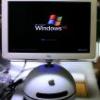
peterg Posted May 22, 2010 Share Posted May 22, 2010 hi all an update on my success with the g4 mods. using information from this blog, i have got a 15" g4 screen working using a dvi-d cable. in the image you see the imac screen - i am using an atx power supply to supply power to run the screen. i am using the dvi-d box from my macbook pro and a standard dvi-d cable is connected to it. as you can see the image is fine. the japanese blog was not quite enough detail on what to do with the b/l of the inverter. i found that if you tied it do +5v via a 1kohm resistor it turned on the screen. however, this meant the screen was on when the computer slept - garbage was displayed on the screen, and it looked like it was harming the inverter. so the fix is to use the 5v off the dvi-d connector, (pin 14) which only gives 5v when the computer is awake. issues as the computer goes into sleep mode, the screen shows random gibberish for a few seconds. i have enc. a pin out. the colours on the left are from my monitor cable - yours may be different. the fantastic thing about this, is that you can use your existing imac screen, and you don't need to pull that bloody swing arm apart! i actually did not pull the screen apart to do this mod at all! also, i can't seem to get dimming to work. i created a voltage divider using instructions from here to get the 0.9 to 3.3 v required. but it made no difference to the screen. so i am pretty happy with this, i can use an itx motherboard with dvi-d output to make an new mod! don't forget to check out my youtube vids! pinouts.pdf Link to comment Share on other sites More sharing options...
Iceman Posted June 18, 2010 Share Posted June 18, 2010 Please, can you explain each LCD cable pinout to the DVI cable? I was on thread you are talking, but i have not figured out how you did that... Please, let me know Link to comment Share on other sites More sharing options...
peterg Posted June 25, 2010 Share Posted June 25, 2010 Please, can you explain each LCD cable pinout to the DVI cable?I was on thread you are talking, but i have not figured out how you did that... Please, let me know hi that pin out i included shows the dvi pin to the colour of the tmds cable/connector inside the mac. remember it is a good idea to keep the shielding on each cable pair when you are connecting a dvi cable to the mac TMDS cable. it takes a while to make the connections take your time and check yourself regularly. i was having some issues with sleep and wake. see vid since i posted that pinout, the inverter pin BL/ON-Off wire should not be tied to 5v. i found that the backlight uses a 3v 30303Hz, 38% duty cycle signal to turn on the backlight. i made a 555 circuit up to generate the signal. if you are familiar with a 555 astable multivibrator circuit, you should be able to make one up. to make a astable multivibrator with a duty cycle less than 50% requires a diode over R2 in the circuit. see http://en.wikipedia.org/wiki/555_timer_IC#Astable_mode i found a resource on the web to calculate the resistor/capacitor combos and used: R1 = 750, R2 = 1300, C = 22nf with a diode over R2 (anode to pin 6) using the 555 circuit helped with this problem a little - there was no 'burn in' with the screen but the corruption was still present during sleep/wake. good luck. Link to comment Share on other sites More sharing options...
gaby333 Posted July 22, 2010 Share Posted July 22, 2010 Some new guide? Link to comment Share on other sites More sharing options...
Recommended Posts