jberg44 Posted September 14, 2011 Share Posted September 14, 2011 This is a case mod of two popular PowerPC iMacs the G4 and the G5. Both of these have been converted to external DVI monitors using a combination of native parts and parts from Apple's 20" aluminum cinema display. These are arranged in a dual monitor setup for the newest generation mac mini, which can be seen underneath the right hand portion of the desk. It is in a 3rd party mount that features very useful front facing USB ports. Both the iMac G4 and iMac G5 are more than just monitors, they give the mac mini extra functionality. The iMac G4's base contains a DVD R/W drive - functioning as an external optical drive. The iMac G5's iSight camera and microphone have been converted to USB making the iMac G5 an external webcam/mic. The iMac G4's Apple Pro speakers connect via iFire to a firewire and 3.5mm jack to complete the setup. The iMac G4 mod: This was originally an all-in-one which used a Penryn Core 2 Duo ECX board, however after difficulties with attempted hackintoshing and the release of the new Sandy Bridge mac mini's I elected to convert this to an external monitor for an external mini. The monitor housing contains the native LCD and inverter. The neck has been modified with wires from the 17" iMac neck as well as wires from the apple cinema display's cable. The cinema display's power brick is at the top of the dome with the power source from an internal optical drive enclosure. The native iMac power plug gets split between these two. An on/off switch for the drive was added to the rear ports as well. The 5.25" SATA DVD R/W drive slides in to where the native superdrive was and the SATA connected to the power and a SATA to USB converter. The cinema display's control board then sits underneath the drive getting power and signaling from the LCD and also supplying 2 powered USB ports. One of the USB ports hooks up to the drive and one additional port is available for use in the rear of the machine. A DVI to HDMI cable yields an HDMI out which plugs into the mini. A completed external USB optical drive and 20" monitor in the iMac G4's case The iMac G5 mod: Initially I had used the case to the first generation (non-iSight) iMac G5. I used the native display but with the LCD controller, inverter, and wiring from the cinema display pictured above. The Cinema Display's cable goes out the back (where the power cord was natively) and the power brick is external. The original iMac G5 was quite bulky and I was using an external webcam/mic until a friend recommended using the iSight. The iSight can be spliced directly to a USB cable and while the mic is spliced to a 3.5mm plug, an inexpensive USB sound card (mic and headphone jacks to USB) can be used to make the microphone USB compliant. The mic and camera then plug into the cinema display controller's 2 USB ports. And then the mod is complete: 1 Link to comment https://www.insanelymac.com/forum/topic/267967-20-imac-g4-and-imac-g5-as-dual-screens-for-mac-mini/ Share on other sites More sharing options...
warlikewings Posted April 14, 2014 Share Posted April 14, 2014 I'm actually about to attempt something like this with my first gen 17" iMac g5, thanks for the info. I'm trying to track down a used Cinema Display or parts from it now... I may end up going with a third party controller, and messing around with the stock g5 power supply, but that's all as a last resort. Link to comment https://www.insanelymac.com/forum/topic/267967-20-imac-g4-and-imac-g5-as-dual-screens-for-mac-mini/#findComment-2012649 Share on other sites More sharing options...
Razzle_Dazzle Posted April 15, 2014 Share Posted April 15, 2014 I am wanting to attempt this in some way. I have an original 23 inch Cinema Display screen with a broke back hinge that is suppose to stand it up. Not an original to the G5 but a later add on wondering how I can rewire the screen to support and external power source and an DVI connection. Link to comment https://www.insanelymac.com/forum/topic/267967-20-imac-g4-and-imac-g5-as-dual-screens-for-mac-mini/#findComment-2012774 Share on other sites More sharing options...
warlikewings Posted April 20, 2014 Share Posted April 20, 2014 I found what appears to be a pretty decent LCD controller on eBay that has hdmi/dvi/VGA/analog video input and audio out (which can be tied into the internal speakers of my g5 case it has it's own inverter and power supply, and though it's more of an easy way out, that may require some case modding, it has potential. @razzle dazzle: while I'm not expert, especially with the cinema displays, and hopefully jberg44 will eventually pop in... I believe the cinema has an LCD controller built in already that can be wired directly to a dvi connection. Check out http://www.dremeljunkie.com Which I think is the OP's own site... I may be wrong. If anyone has tutorials and pin config for you to use during rewire, he will. Also, why would you want to build in an external power source rather than use the stock power supply for the 23" Cinema Display? Considering it has an LCD controller already onboard and would just need to be wired up to a dvi port internally, you shouldn't even have to mess with the power supply at all. Link to comment https://www.insanelymac.com/forum/topic/267967-20-imac-g4-and-imac-g5-as-dual-screens-for-mac-mini/#findComment-2013939 Share on other sites More sharing options...
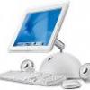
Razzle_Dazzle Posted April 20, 2014 Share Posted April 20, 2014 while I'm not expert, especially with the cinema displays, and hopefully jberg44 will eventually pop in... I believe the cinema has an LCD controller built in already that can be wired directly to a dvi connection. Check out http://www.dremeljunkie.com why would you want to build in an external power source rather than use the stock power supply for the 23" Cinema Display? Considering it has an LCD controller already onboard and would just need to be wired up to a dvi port internally, you shouldn't even have to mess with the power supply at all. Thank you for the link, I was sort of able to find his tutorial for a 20 inch Cinema Display but since it was an old mod the photo were no longer there. I can follow what he has done through his instruction but I prefer to see it to know that I am not wiring the screen wrong. I didn't know if the monitor came with an internal power controller board or not. I Know the original GPU in the G5 case has a uncommon looking DVI port and the screen connects to it has the ability to not only power the back light and the display as well as turn on the system with a touch of the display power on button. Standard DVI I doubt has enough voltage to power on a display and the back light. Since waiting for any information I found this link which shows me how to pin out the display, though the image of the wiring are a massive mess it is hard to know how he managed to wire it all lol Link It is how my apple monitor looks like, I did a lot of Google search to figure out if my monitor is a Cinema display or Studio. I can not really tell the difference honestly but in either case it is a 23inch display. I read that the connection type is known as ADC. The power supplied to the screen itself is 25 volts. He adapted a 24 volt and 1.5amp to the screen which was plenty enough for the screen. I again doubt that standard DVI connection will actually have 25 volt. Link to comment https://www.insanelymac.com/forum/topic/267967-20-imac-g4-and-imac-g5-as-dual-screens-for-mac-mini/#findComment-2014032 Share on other sites More sharing options...
warlikewings Posted April 20, 2014 Share Posted April 20, 2014 Hmm, is this a currently working apple Cinema Display? If so, you probably just need an adapter for the display port connection to go to dvi. I'm not saying you shouldn't attempt a mod, but I think for what you're trying to do, you may not need to. I believe the weird dvi input on your screen is called display port, and apple has display port to dvi, and probably display port to hdmi adapters available. 1 Link to comment https://www.insanelymac.com/forum/topic/267967-20-imac-g4-and-imac-g5-as-dual-screens-for-mac-mini/#findComment-2014053 Share on other sites More sharing options...
Razzle_Dazzle Posted April 20, 2014 Share Posted April 20, 2014 Hmm, is this a currently working apple Cinema Display? If so, you probably just need an adapter for the display port connection to go to dvi. I'm not saying you shouldn't attempt a mod, but I think for what you're trying to do, you may not need to. I believe the weird dvi input on your screen is called display port, and apple has display port to dvi, and probably display port to hdmi adapters available. Yes the display last time check was working very well. I checked for adapter for a Display port to Dvi I don't think that is what I am looking for :/ The connection type is known as ACD It is a type of display connection but it is similar as DVI with an extra line for the 25v to power the display, Normal DVI connection does not have the extra voltage. Which is why no window PC turns on with a display button. Link to comment https://www.insanelymac.com/forum/topic/267967-20-imac-g4-and-imac-g5-as-dual-screens-for-mac-mini/#findComment-2014086 Share on other sites More sharing options...
warlikewings Posted April 21, 2014 Share Posted April 21, 2014 Just looked into it, there is an ADC to DVI connection adapter made by apple that you should be able to use. I apologize, I didn't know what your connection was after all, but thanks for the update. If you do decide to do some sort of mod, post a link here to your thread so I (and others) can follow your progress. I'll do the same when I manage to get my LCD controller board ordered. Link to comment https://www.insanelymac.com/forum/topic/267967-20-imac-g4-and-imac-g5-as-dual-screens-for-mac-mini/#findComment-2014128 Share on other sites More sharing options...
MiniHack Posted May 4, 2014 Share Posted May 4, 2014 Not been on here for a little while and saw this posting. Just thought I would mention that I did a Studio Display conversion from an ADC connection to HDMI connection a while back and for my own use I did a bit of a write up that I never quite finished…I do though still have all the pic.s, pinouts and my notes on the procedure so thought it might help for me to copy it and put it all up here. I found that the simplest way was to take an HDMI cable, cut the end off it and then wire up all the ends of the cut off cable directly to the corresponding wires on the Studio Display so that the display now instead of having a flying ADC cable has a flying HDMI cable. For the power supply I simply wired up a power socket jack to the case of the Studio Display and put it in place where the old USB 1.1 hub was located and used a cheap universal laptop supply that I set to 24v output. What I didn't do, but should have done (and could not be bothered to do after I had finished the project!!) was to actually connect the USB "in" to the display to a USB cable. The reason I found I should have done that is because without it there was no way within OS X to change the brightness - so brightness is on full (which is not terrible, but not ideal). Brightness can be changed in Windows, but for OS X unless you hook that up then system preferences can not change it. So if you do a diy re-wire like me then remember that small fact. Here are the pic.s I took while working on the job and I have attached the wiring diagrams that I found and used…. Finally, here is a copy of the write up I made, but never published! I bought an old Apple Studio Display recently off eBay. It is one of the 15" models with the ADC cable. I wanted to convert the display for HDMI to use, and had not seen any walkthroughs for this procedure - although there are a number of walk throughs for DVI conversion. First thing to get is a universal AC power adapter. I got one with a voltage switch on the side for less than £10. A 60W adapter is sufficient and it must be capable of 24v output. I also got a DC power inlet socket. I had the luxury of a ADC equipped Cube to check the monitor forked properly before I started, so I figured it would be a good first test if I saw if the Cube could display to the screen if I disconnected the power from the ADC cable and replaced the display power with the power from my adapter. This way I would then at least know when trouble shooting later that I had a good power source - one less unknown!. So onto striping down the display: Here I am removing the power plug from the display, cutting the cord and re-wiring it for use with my own adapter: Carefuly now making sure thet the 25v line from the ADC cable cannot short out inside the case I then (with power coming from my adapter now) fired up the cube and sure enough it booted through to the desktop….. Now time to get dirty with the cable and to make the display unusable by an original cube (!). My initial plan had been to re-use the original Apple cable and just solder on the needed wires to an HDMI plug. I bought a solderable plug off eBay and to cut a long story short…..after getting half way through the hack I decided the soldering job was too delicate for me…..so instead I took a spare HDMI cable and took that apart. However you do this though, stripping the Apple ADC connector down is useful to see the wire colors and how they are grouped and which pins they go to on the ADC connector. If like me you take the easy way out then the following strip down of the connector end is not needed. You just need the results so you can find what the cable colours and connections at the display interior mean. So I suggest you skip to the ADC wiring section to avoid boredom. This is my strip down of the original Apple connector in the next few photos. Note the horrible gunky stuff they put around the pins to stop you getting at them! I stripped of as much goo as I could to note down what cables went where. ADC WIRING: Here is a pinout of the ADC connector (looking from the male end). The signals we actually need to connect to with our HDMI connector (again cutting a long story short!) are the TDMS lines for TDMS channels 0, 1 and 2. Each of these has a positive lead, a negative lead and a shield. We also need the TDMS clock, DDC data, DDC clock and clock return Apple seems to enjoy reversing conventions. Please note that in the apple connector all the white leads are positives, whereas in the HDMI lead I was using the whites denoted negatives. So with Apple NEVER assume that connecting like colours together will work….. ADC CABLE ANALYSIS The following set of leads come grouped together (for shielding): TDMS Data 0: black(-), white(+), shield TDMS Data 1: Pink(-), white (+), shield TDMS Data 2: Orange(-), white(+), shield TDMS clock: Brown(TDMS clock -), white(TDMS clock +), shield Other single wires we need: Brown from C5 (DDC return), blue (DDC data line), yellow (DDC clock line) , The rest (that we have no interest in): orange(LED), red (soft power), Grouped together : green, white, black (USB data lines + - and return line) Large leads 2 Red, 2 black. (25V and Gnd returns) HDMI cable wiring: See pinout! I won't guess the colours in your cable but from the pins within the cable we need to be connecting up all of the following pin groups for which the descriptions match the colour coded cables listed above: HDMI CABLE ANALYSIS As I mentioned earlier, do not make any assumptions about the colouring of signals in the HDMI cable matching those of Apple- in my HDMI cable all the white cables in the TDMS groups were connected to negative lines, whereas in the Apple cable they were the positive lines….for that reason I am deliberately NOT telling you the colours I found in my HDMI cable and you must make a note of what you find on a pin by pin basis. it's a simple procedure, note down the colours etc. according to the HDMI pin you remove them from. TDMS channel 0, 1, 2 [0:+ (pin 7 HDMI) shield (pin 8 HDMI) - (pin 9 HDMI); 1: + (pin 4 HDMI) shield (pin 5 HDMI) - (pin 6 HDMI); 2: + (pin 1 HDMI) shield (pin 2 HDMI) - (pin 3 HDMI)] TDMS clock + (pin 10 HDMI), TDMS Clock -(pin 12), Shield (pin 11 HDMI) DDC clock(pin 15 HDMI), DDC Data(pin 16 HDMI), DDC return (pin 17 HDMI) This leaves us with: Hot Plug Detect (Pin 19 HDMI); +5v power (pin 18 HDMI); CEC (pin 13 HDMI). These last three I did not know what to connect to where, I discovered that CEC does not need to be connected to anything; Hot plug detect NEEDS to be pulled to a high voltage; probably the +5v pin from the cable does not need to be connected, but I connected it up to the red (soft power) lead of the display. To deal with the Hot plug detect (which when left disconnected was the one thing that seemed to be needed as the display was not seen by the PC) I actually connected it to the +5v line that is used internally within the display for powering the USB hub. I figured that as I had no use for running a USB cable to the display just to then get two USB 1 ports I could use the 5v to do my hot plug detect. I did not use a resistor here, because I guessed that the USB hub supply would be limited and that the cable would only draw a small current, some people suggest using a resistor pull up to a 5v supply but my way seems to work fine…. Hope this salvaged info from my records helps you or someone else along!! ADC Cable Pinout.pdf 1 Link to comment https://www.insanelymac.com/forum/topic/267967-20-imac-g4-and-imac-g5-as-dual-screens-for-mac-mini/#findComment-2017290 Share on other sites More sharing options...
warlikewings Posted May 4, 2014 Share Posted May 4, 2014 Wow, thanks for all of this! I'm going to really look at it and see if I can make something like that work with the g5. The difference is that my g5 doesn't have a flying ADC cable because it's originally an all in one computer. What it does have is an Lvds cable I believe, that connects the LCD to the logic board (which is dead and not worth replacing, considering the machine itself is very obsolete by now) I am considering installing one of those LCD controller boards from eBay into it, which has hdmi/VGA/dvi/and possibly an analogue a/v style video input. I'm not sure if I trust myself enough to hack up the original computer power supply or if I want to power it some other way, and I'm also trying to figure out a way to make use of some of the exposed port cutouts on the back, maybe using a usb hub or something would be a good idea. It is only 17" and almost wouldn't seem worth doing, but I'm going to attempt this when funds permit, and I have enough info on it, mainly for the fun of the mod. I had a few cool ideas for the mod, but this one won out due to it's functionality after. Link to comment https://www.insanelymac.com/forum/topic/267967-20-imac-g4-and-imac-g5-as-dual-screens-for-mac-mini/#findComment-2017291 Share on other sites More sharing options...
MiniHack Posted May 4, 2014 Share Posted May 4, 2014 Yeah, what I put up is just for the old style Cinema Displays/Studio Displays. I have a few of them here actually, really not sure what I'll do with them eventually, but it seems a shame to be just chucking them away for almost nothing when they work well enough and are brilliantly retro. The conversion process can be a pain…..but in the end at least you end up with something that works with modern hardware while looking pretty cool. Good luck with the G5. I am sure I have seen some conversions documented. Certainly I know over on the TonyM forum in the "Workshop" section there are some specific conversions for the G5 to hook up to an Intel NUC - those write ups will probably help you out quite a bit. Link to comment https://www.insanelymac.com/forum/topic/267967-20-imac-g4-and-imac-g5-as-dual-screens-for-mac-mini/#findComment-2017302 Share on other sites More sharing options...
warlikewings Posted May 5, 2014 Share Posted May 5, 2014 Man, I'd love to run across someone in my area looking to unload some cinema/studio displays, or even an old g4 that's a slick looking design too. I miss when apple products had unique and cool designs to them. They used to be more artsy. Thanks for the info though, I do occasionally pop over to that other page, I usually find this one to be more helpful though, but I don't believe in limiting my resources. I've learned a bit from the other site too. Link to comment https://www.insanelymac.com/forum/topic/267967-20-imac-g4-and-imac-g5-as-dual-screens-for-mac-mini/#findComment-2017331 Share on other sites More sharing options...
Recommended Posts