MiniHack Posted May 7, 2013 Share Posted May 7, 2013 Hi all, Another project in progress for me since last week is this one. At the moment it feels like I may have bitten off too much. Background I've done a few Cubes already, the last couple used the original CUbe heatsink to cool them and worked well. This time I wanted to go for something different and I took it on because I already had the parts for it here. Bits being re-used from other builds are: Zotac Z77 wifi board Corsair RAM, Corsair H80, 160W PicoPSU, mSATA drive, Old Cube bits. New parts: i7 3770k I'll admit this is a bit of a silly power crazed build. Having done a Cube with an i5 2500K I wanted to up the Geekbench scores and see whether the unused H80 I had could be used in a Cube. Of course, it couldn't be fully enclosed, so the first thing to happen was this: No laser cutting here, just good old dremeling - this case eats dremel disks!!! The discolouring is as this particular old case originally had my old Mini in a Cube inside it that my wife has had for a number of years. It was re-sprayed white at one stage and after being knocked about by me it now needs stripping and painting again. This great big hole is for the radiator to expel heat out the back of the Cube - the plan being that from the front view the Cube looks pretty much normal. The same Cube case had a cut down casing and was used on its side, so I cut that case up too: Here you see it and the removed front plate of the Cube sitting in it as a trial. After this, I did a dummy fit up with an old ITX board inside the Cube cage: Shown here is a Noctua 120 PWM fan (for quiet cooling) mounted onto the radiator of the H80 and held by the original hard drive cage. As a first fit I was happy that this would be a good place for rad mounting and with a bit of luck just the one 120 fan might do the job if I can get a good air flow in from top and bottom of the Cube. If I am not so lucky I can put another 120 fan on the outside at the back of the Cube and make it removeable. So, as the drive cage is normally front mounted and I want to move it to the back (and Apple did not make these things symetrical) I needed to do some mod.s to the cage and the inner can. Basically, the Cube switch is usually over the motherboard side but is a squeeze there. So I ended up spinning the Cube and re-cutting the inner cage. So first job was cutting another hole for the touch switch and making some fixings for it -using my favourite thing of the moment rivet nuts. Needed to do the same thing to the can: The hole was cut using a hole saw and turned out better than I had hoped (one slip costs a lot of time!). I went on to cut the tubes from the H80 - as there was no way it would fit with the long pipes - and drained the fluid. More to come as I get time..... 2 Link to comment https://www.insanelymac.com/forum/topic/288395-water-cooled-g4-cube/ Share on other sites More sharing options...
Baudouin Posted May 7, 2013 Share Posted May 7, 2013 Nice MiniHack. I am jealous, I have one working Cube, another case and full of Cube parts, but not the money to buy the parts to build a Hackintosh for the moment, maybe later. And your build will be very inspiring and big help. 1 Link to comment https://www.insanelymac.com/forum/topic/288395-water-cooled-g4-cube/#findComment-1913436 Share on other sites More sharing options...
ElAwesome Posted May 7, 2013 Share Posted May 7, 2013 Hell yes a WC'ed cube I'm surely gonna follow this one! 2 Link to comment https://www.insanelymac.com/forum/topic/288395-water-cooled-g4-cube/#findComment-1913439 Share on other sites More sharing options...
MiniHack Posted May 7, 2013 Author Share Posted May 7, 2013 Nice MiniHack. I am jealous, I have one working Cube, another case and full of Cube parts, but not the money to buy the parts to build a Hackintosh for the moment, maybe later. And your build will be very inspiring and big help. Thanks Baudouin. Money is the limiting factor for me too. That's why mostly I am tearing apart other builds to make new ones. The big expense on this one is the i7 processor....but that is probably at the end of the Cube build going to be ripped out and put into the G5!! At least if it doesn't work then I can just pretend this build didn't happen (!). I'm excited though as I am always looking for something different in how to mod these old Apple cases. Hell yes a WC'ed cube I'm surely gonna follow this one! Thanks - I must admit though to being jealous of your desk!!! 1 Link to comment https://www.insanelymac.com/forum/topic/288395-water-cooled-g4-cube/#findComment-1913478 Share on other sites More sharing options...
MiniHack Posted May 9, 2013 Author Share Posted May 9, 2013 Not much to update right now. Just decided though that I can fit two fans inside the Cube with a couple of small mod.s - so I have bought two of these: http://www.kustompcs.co.uk/acatalog/info_25094.html At 15mm and by modifying the drive holder cage I can get these in push pull on the radiator. I can then use a manual fan control to turn them up or down. I prefer this as it will give me potential for more through cooling and mean I don't have to think about the need for bolting a fan to the back of the case. The space I have inside the cube for the fans and radiator is 75mm and these will just fit in okay on either side of the H80 radiator. This means the only thing I might have to bolt on to the back of the case (if things don't work out ideally) would be a small reservoir. Link to comment https://www.insanelymac.com/forum/topic/288395-water-cooled-g4-cube/#findComment-1913818 Share on other sites More sharing options...
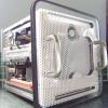
MiniHack Posted May 9, 2013 Author Share Posted May 9, 2013 Just doing a bit of browsing and thinking of spending more money (again!) on this: http://www.alphacool.com/product_info.php/info/p972_Alphacool-NexXxoS-XT45-Full-Copper-120mm-.html/XTCsid/nutr2br7m8jrk2obah4bnmmsj http://www.alphacool.com/images/product_images/popup_images/972_4.jpg Reason I am excited about this as a possibility is the all copper construction and the 6 possible connections. This should make getting air out of the loop a lot easier as I can connect up the closed loop and use the extra plugs to expel air from and do a final fill before s*crewing in the two top end plugs. Only question in my mind is if this radiators flow would not suit the integrated pump/block....what do you guys think? Link to comment https://www.insanelymac.com/forum/topic/288395-water-cooled-g4-cube/#findComment-1913834 Share on other sites More sharing options...
ElAwesome Posted May 9, 2013 Share Posted May 9, 2013 How do you think it wouldn't suit the pump/block? As long as you get the right fittings, everything should work (in theory). The rad itself is probably perfect for your build, I'd say the money is well spent there. 1 Link to comment https://www.insanelymac.com/forum/topic/288395-water-cooled-g4-cube/#findComment-1913847 Share on other sites More sharing options...
MiniHack Posted May 11, 2013 Author Share Posted May 11, 2013 Small update: The Alphacool radiator and 2 Phobya fans are on their way. I am re-thinking the design slightly and am working on creating a sort of structural cassette out of the fan and radiator and drive support cage combination. I think I can use existing structural parts inside the Cube inner cage to get a good location of all the parts and effectively join the drive holder to the latch mechanism side supports. I am also thinking now of getting rid of the handle latching mechanism itself to open up the centre of the Cube a little more. This will let the fans breathe more easily and cool my radiator more effectively. As a side benefit it will also allow my mobo to re-locate a couple of mm more to the centre so I may be able to gain back the space to have a slot loader in the Cube. I can't make too many cuts until the actual radiator and fans arrive here but a plan is formulating..... The next problem though will be the question of how to make the core easily removeable without having the latch mechanism - I could always do it like shown in my avatar, but I'm also looking at other ways. 1 Link to comment https://www.insanelymac.com/forum/topic/288395-water-cooled-g4-cube/#findComment-1914233 Share on other sites More sharing options...
MiniHack Posted May 12, 2013 Author Share Posted May 12, 2013 Another small update - Following my thoughts on getting rid of the handle latching mechanism I have now decided definitely to remove it. It just takes up too much room that could either be used for something useful or could be freed up to help airflow. My solution is for the interior of the cage: 1. replace the left over heatsink sides with lower profile aluminium channel - so that the side parts stay rigid when I take away the original parts. This will increase the area inside the Cube without causing a loss in strength; 2. Make a plate that crosses from left to right to join the side pieces (with their now new inner rigid channel), the plate has 120mm fan hole for the "inside" fan (and with extra holes or gaps to route cables and pipes); 3. Make a similar plate that crosses from left to right to join the back left and right sides of the drive holder together which also has a 120mm fan hole etc. for the " outside" fan and rivet/bolt/weld this plate to the drive holder. 4. Cut the front of the drive holder. These things will now exactly take and support my new radiator and push pull fan combo as the two new plates will sandwich them together. What remains of the drive holder and the new central part of the Cube will locate this sandwich of parts securely into position. And then at the top of the Cube: Get some M6 Rivnuts to change the hole (in the inner cage) that the two top screws used to go through into a strong threaded connection. Use some nice flanged M6 bolts that go through the original two holes in the top of the perspex case to secure the inner Cube cage in place. Keep the outer "can" part as it is and have it supported when empty by the middle vent connection. I think this should work okay. The M6 bolts have a head outer diameter of 10mm which matches the recess for the original captive nuts on the Cube - so they will sit nicely there. Also the acrylic at the top is 10mm thick (7mm thick at the recess) so should be able to take the weight. Finally, the M6 rivnuts I have chosen have exactly the right diameter to fit the existing holes in the inner cage without need for any more drilling. I can also experiment with hanging the Cube internals "naked" in the case and see how I like the different looks and compare how it keeps temps in check in the different modes. 1 Link to comment https://www.insanelymac.com/forum/topic/288395-water-cooled-g4-cube/#findComment-1914578 Share on other sites More sharing options...
Baudouin Posted May 12, 2013 Share Posted May 12, 2013 Waow, this is a deeply precisely thought of how to proceed. You will write an How-to after you have finished, I guess . 1 Link to comment https://www.insanelymac.com/forum/topic/288395-water-cooled-g4-cube/#findComment-1914594 Share on other sites More sharing options...
MiniHack Posted May 12, 2013 Author Share Posted May 12, 2013 When all the different pieces arrive I will try to remember to take lots of photos! I think that the actual watercooling may be quite simple in the end, it is the planning that takes the time. I am super pleased to have found that Alphacool radiator though as it seems to be exactly what is needed for this kind of mod inside what is quite a small case and it should also be much more efficient than the corsair one. So while this mod. has now taken a different direction than when I started I am hopeful that the end result will be a lot better. 1 Link to comment https://www.insanelymac.com/forum/topic/288395-water-cooled-g4-cube/#findComment-1914600 Share on other sites More sharing options...
MiniHack Posted May 14, 2013 Author Share Posted May 14, 2013 Some days you just don't get it right. I bought some of these: http://www.ebay.co.uk/itm/Countersunk-Head-Open-Steel-Grooved-Rivet-Nuts-Rivnuts-Nutserts-Blind-Nut-/310506237332?pt=UK_BOI_Metalworking_Milling_Welding_Metalworking_Supplies_ET&var=&hash=item484b9d2d94 M6 Stainless steel rivnuts. Of course, I should have realised that the force needed to use these stainless steel fixings was going to be huge! I have now got some aluminium ones coming that hopefully will be useable. .....on the bright side the Alphacool radiator and Phobya slim fans have arrived and they will look superb. Link to comment https://www.insanelymac.com/forum/topic/288395-water-cooled-g4-cube/#findComment-1915105 Share on other sites More sharing options...
Baudouin Posted May 14, 2013 Share Posted May 14, 2013 I understand better now why they sell some air pressure revolver rivetnut. 1 Link to comment https://www.insanelymac.com/forum/topic/288395-water-cooled-g4-cube/#findComment-1915133 Share on other sites More sharing options...
MiniHack Posted May 14, 2013 Author Share Posted May 14, 2013 ....and the winner for the Worlds smallest water cooling loop is: I understand better now why they sell some air pressure revolver rivetnut. Jean Claude Van Damme would struggle using my little rivet gun. Epic fail. 1 Link to comment https://www.insanelymac.com/forum/topic/288395-water-cooled-g4-cube/#findComment-1915135 Share on other sites More sharing options...
MiniHack Posted May 15, 2013 Author Share Posted May 15, 2013 Keeping this build quiet and within the power limits of the pico psu are two of the most important parts of this build, as well as seeing if it can cope with a mildly overclocked 3770k. As part of this I am trying to test everything for power consumption/noise before it goes in to the Cube. Just been test running the Corsair pump and Alphacool radiator combination, along with the two Phobya fans hooked up to a simple Asetek fan controller (literally about £3 inc. postage). Noise from the fans at full tilt is reassuringly loud with a good through breeze, but when I use the controller it can be turned down to something less than audible. Power draw at the wall from the combination of pump, and two fans is 14w (inc the draw from the ATX PSU itself that I am testing them on) at max settings and goes down to around 9 or 10 at lower speeds. Disconnecting the fans and pump and measuring just the draw from the PSU with fan shows that as taking about 5 watts - so in reality my fans and pump combo is taking a max of about 9W. Seems okay. The only other power consumption apart from main board and processor will be by myToshiba SSD (that I think is supposed to be an incredibly small 1.5W) and a slot loader that supposedly will run from a single USB input and therefore about 2.5W max. In theory then I should have a maximum of up to 130W allowable for the onboard consumption of CPU, board and RAM for any overclock experiments.... So far so good. 1 Link to comment https://www.insanelymac.com/forum/topic/288395-water-cooled-g4-cube/#findComment-1915304 Share on other sites More sharing options...
MiniHack Posted May 15, 2013 Author Share Posted May 15, 2013 A couple of shots for scale on how this compares to the internal size of the Cube: 1 Link to comment https://www.insanelymac.com/forum/topic/288395-water-cooled-g4-cube/#findComment-1915333 Share on other sites More sharing options...
MiniHack Posted May 16, 2013 Author Share Posted May 16, 2013 So, a bit of an update today. The aluminium rivetnuts arrived and so did a aluminium plate I had cut for the Cube. So it was now time to get the files and dremel out again and do a bit more fitting up. These are the rivetnuts for the new hanging system so I can get rid of the handle assembly: Tip: if you have a cheap hand operated rivet tool M6 rivet nuts in aluminium are about the limit that I think you can mount properly! Still, this open style of rivet nut will flush mount and give a really strong thread. First I had to open up the holes in the inner cage a little to take the rivet. Then they went in fine This is the result: Opening up the holes in the perspex and also a little in the top plate for the outer case meant the Cube will then be able to be secured in the case using some cap screws. The aluminium laser cut turned out well. and here you can also see how I have cut out the handle section (I'll replace this bit later with a more open mesh). So, this is where it is right now. Still working things out and fitting them up but it is coming together. 4 Link to comment https://www.insanelymac.com/forum/topic/288395-water-cooled-g4-cube/#findComment-1915646 Share on other sites More sharing options...
ElAwesome Posted May 19, 2013 Share Posted May 19, 2013 Coming along nicely! 1 Link to comment https://www.insanelymac.com/forum/topic/288395-water-cooled-g4-cube/#findComment-1916244 Share on other sites More sharing options...
MiniHack Posted May 20, 2013 Author Share Posted May 20, 2013 Coming along nicely! Thank you. Just also bought this one: http://www.ebay.co.u...984.m1438.l2649 I couldn't resist it as I am needing to drive down that way soon for a family celebration so I can call in and collect on the way. I have modified my backplate design a little and that should be with me in the next week or so and will also be the basis for a new laser hive product line. Basically I have made a complete backplate outline which, though I am cutting it for my own mobo pattern, I will easily be able to adapt for a standard ATX rectangular IO pattern. That new plate will then be bondable to the original back so it can be blended in to the original plate and allow the user to either keep the original handle mechanism (or get rid of it) and to either keep the original small holes on the "wide" side of the cube or get rid of them. If the user wants to get rid of them it will then be an easy conversion to add a wider (more open) mesh for higher airflow if wanted - which is what I'll be doing to mine. This will be a new design to add to my website and it will be able to be ordered with custom re-positioning of the rectangular ATX IO to wherever the modder wants to put it - all I will need to ask for customising is the relative position of the bottom left corner of the ATX shield. It won't be a full conversion kit (there are too many different ways of Cube modding to be able to do that). But it will let people have an easy way to tidy up their own backplate, it will add a few more millimetres of wiggle room front to back for PicoPSUs and it will give choice and an easy way to customise the air paths by opening new ones up or closing some off. I am aiming at a price point of just £18 for the plate to retail to the customer and it will be a special order item because of the need for the plate to have the ATX shield in the place of user choice (and also to account for either full height or half height ITX shields). 1 Link to comment https://www.insanelymac.com/forum/topic/288395-water-cooled-g4-cube/#findComment-1916490 Share on other sites More sharing options...
fatez Posted May 31, 2013 Share Posted May 31, 2013 any news? Link to comment https://www.insanelymac.com/forum/topic/288395-water-cooled-g4-cube/#findComment-1919061 Share on other sites More sharing options...
MiniHack Posted June 1, 2013 Author Share Posted June 1, 2013 any news? Yes, will do an update tomorrow if I get a chance! This is a fun build and is one where a solution to one problem then has a knock on effect on how and where to do other things. The cooler now is mounted nicely in the cube and next job is to get the mobo mounted.....then I can sort the pipework and see what room is left. I definitely have room for mounting a 7mm thick SSD above where the airport antennas fix on one side, and I am also thinking about where to put the fan controller board, USB extension and if possible DVD drive. Getting rid of the heat sink and handle mechanism really clears up a good amount of space to play with. 3 Link to comment https://www.insanelymac.com/forum/topic/288395-water-cooled-g4-cube/#findComment-1919248 Share on other sites More sharing options...
MiniHack Posted June 2, 2013 Author Share Posted June 2, 2013 Here is a link to a youTube video just oploaded. http://youtu.be/Gn_FbjipYfA Today I worked out the length and connectors for the cooling in the case and hooked that all up. The radiator and push pull fans are shown here fixed by the drive braket and the centre bracket. Here the system is inverted and filled and running. At first there was a lot of air in the loop and the pump very noisy, air is easy to get out of this loop though and a few top ups later the pump is running very quiet. Fans here are hooked up to the corsair block and running full speed. Even so, they are not too noisy. The inner fan is soft mounted and the outer is hard mounted to the case parts. I might see if I can change the outer mount to a soft one too as this fan produces noticeably more noise. 1 Link to comment https://www.insanelymac.com/forum/topic/288395-water-cooled-g4-cube/#findComment-1919385 Share on other sites More sharing options...
MiniHack Posted June 4, 2013 Author Share Posted June 4, 2013 Had some time today to progress a little further. I'll post some pic.s tomorrow hopefully, but the internals are now almost mapped out. I had been wondering how best to secure the mobo in the cube core - as the corner struts unhelpfully make it awkward to fix a tray. Today though I bit the bullet and made a support that joins the aluminium handle support rails to each other (to give it some extra strength and resist against twisting now that the heatsink has gone) and also fixed some threaded inserts into that support to take standoffs that will attach to the top of the mobo. In this way, instead of the usual support from underneath it is suspended from above. This extra support piece and the mobo fixing means I can build everything up without having the top or bottom of the cube in place. Also wired my push pull fans into a single fan plug and then mounted the fan controller board to be at the bottom rear of the cube to make fan speed adjustments an easy step. Last thing today was to re-wire the Corsair H80 block so it will draw it's power from the CPU fan header. I know the pump only uses 4W and as I am not using it to actually feed power to the radiator fans this convenient method saves a lot of messy wiring. Just plug the short lead in and it's done. Wiring is one thing I am trying to be really neat with on this one and my aim is not to have to attach a flying molex trail from the pico PSU. SO my solutions to this are: 1. The two fans will take their power from the fan controller and that will take 12v directly from where the mains adaptor comes in; 2. The Corsair block powered from a fan header. 3. (And I think this should work) for my 500GB SSD the power draw is max of 2W. As the SATA data plug is right next to a USB 2.0 header I am intending to use just the power from a dual USB header into a SATA power connector for a minimal routing of 5v and GND power to my SATA drive. I have never seen anyone do this, but I presume that as I have seen external USB devices use a power only connection from a USB port that there is no reason why I shouldn't be able to do that internally. By doing these three things I can reduce the connectors going to the pico psu down to just the CPU power plug. 2 Link to comment https://www.insanelymac.com/forum/topic/288395-water-cooled-g4-cube/#findComment-1919834 Share on other sites More sharing options...
MiniHack Posted June 5, 2013 Author Share Posted June 5, 2013 Latest pic.s This pic shows the core of the cube without the bottom plate. Here you can see the three plates I made up that hold the core parts together. First plate at the top of the shot is the metal plate that holds the outside fan and is bolted to the original drive carrier. The second plate is a 5mm black perspex plate that fixes to one side of the original handle guide / Heatsink retaining pieces and the third plate fixes to the other side of the same pieces. Here is a closer shot of the first piece: and the second piece: And in the shot below you can see that the third piece is also used to suspend the motherboard via standoffs: In this one you can see looking from the front plate down into the cube that the central area I have tried to keep as clear of clutter as I can - the water pipes have to go here and this is also the area that the fans will draw their air from. Here are two side views showing how the SSD will fit. Here you can also see the SATA power to USB power cable I made up to keep the wiring tidy. The 7mm SATA drive sits nicely to the side of the radiator and fan combination and there would be room for another SSD on the other side too (not planning on one for this build though!). 3 Link to comment https://www.insanelymac.com/forum/topic/288395-water-cooled-g4-cube/#findComment-1919963 Share on other sites More sharing options...
Baudouin Posted June 5, 2013 Share Posted June 5, 2013 Great job in this tiny Cube space. Congratz. 1 Link to comment https://www.insanelymac.com/forum/topic/288395-water-cooled-g4-cube/#findComment-1920113 Share on other sites More sharing options...
Recommended Posts