Baudouin Posted August 22, 2008 Author Share Posted August 22, 2008 oh wow its just 2 molex cable, thanks gonna make a new diagram check it out to see if its fine or any errors mistakes and such Perfect !! Some details: 1. Just show above the plastic piece which block the plug onto the mobo to indicate up and down. 2. If two four wires square plugs are used they will fit and will block as I did : http://forum.insanelymac.com/uploads/month...09252_thumb.jpg Link to comment https://www.insanelymac.com/forum/topic/93600-my-nearly-finished-hack-the-tosh/page/3/#findComment-864883 Share on other sites More sharing options...
teknojunkie Posted August 22, 2008 Share Posted August 22, 2008 k all change that up Link to comment https://www.insanelymac.com/forum/topic/93600-my-nearly-finished-hack-the-tosh/page/3/#findComment-865450 Share on other sites More sharing options...
teknojunkie Posted August 22, 2008 Share Posted August 22, 2008 added a couple tweaks and your suggestions Link to comment https://www.insanelymac.com/forum/topic/93600-my-nearly-finished-hack-the-tosh/page/3/#findComment-865479 Share on other sites More sharing options...
Baudouin Posted August 22, 2008 Author Share Posted August 22, 2008 added a couple tweaks and your suggestions No no amantheboy, you will shortcircuit the HDD's and the DVD. One ATX plug can be used as is but the other one must be changed into black and red (5V). Some mod will be needed too, I forgot to mention, because the plug has rond and square holes which won't match the 8 wires plug holes. Just add another draw on the diagr with black and red and it will perfect. And set the 8 wires draw as before, twice yellow, black, black, red. Sorry for the confusion. And people, always test before use with a simple fan with black and volt wires connected to the P3 molex connector to control if the 12V and the 5V are connected at the right place before connecting anything, HDD or DVD. Edit 25/08/08 : Interessing comments from TorqueX86 : post 50 I tried his method with and old PSU plug; the PSU wires have to be replaced of course : Link to comment https://www.insanelymac.com/forum/topic/93600-my-nearly-finished-hack-the-tosh/page/3/#findComment-865577 Share on other sites More sharing options...
teknojunkie Posted August 22, 2008 Share Posted August 22, 2008 oh ok i got it like this ? or this? Link to comment https://www.insanelymac.com/forum/topic/93600-my-nearly-finished-hack-the-tosh/page/3/#findComment-865622 Share on other sites More sharing options...
Baudouin Posted August 22, 2008 Author Share Posted August 22, 2008 oh ok i got it like this ? Yeeesss ; That's nearly perfect!! I've just noticed that the ATX plugs are not well oriented. They must match the 8 wires plug. So the piece of plastic which maintain the plugs together must be oriented above, what means the colors must match too. I will take the time tomorrow to photograh better my plugs and upload them. Link to comment https://www.insanelymac.com/forum/topic/93600-my-nearly-finished-hack-the-tosh/page/3/#findComment-865679 Share on other sites More sharing options...
Baudouin Posted August 23, 2008 Author Share Posted August 23, 2008 External panel in two pieces is attached onto the frame, apple logo draw on paper painted in grey to visualize the mesh panel. Will add comments and pictures on aqua-mac.com and paste here later... Update done reply 41 @ http://aquamac.proboards106.com/index.cgi?...=469&page=3 comments and pics follow on this forum Edit 23/08/08 10.20 PM (Brussels time), Some pics : view of he case with the door panel attached and closed (divided in two parts, the tiny linear mark at the bottom is the separation line) : pics of opening of the acryl door panel (notice that the bottom part of the acrylic panel visible on the previous pix has been removed to free the space needed for the movement of the opening door) the door is completely open: view with case lying on the side panel and open door from the inside : view with case lying on the side panel and open door from the outside : I cut the apple logo (four different sheets) on paper and pin on the wall to visualize the opening I will make on the mesh panel to cover the edges of the external acryl panel. This is the one I will use, maybe a little wider on the right side? Link to comment https://www.insanelymac.com/forum/topic/93600-my-nearly-finished-hack-the-tosh/page/3/#findComment-865865 Share on other sites More sharing options...
Baudouin Posted August 23, 2008 Author Share Posted August 23, 2008 Here are the pics : The plug is positionned like this, plastic piece above the two ATX modded plugs : yellow, black, black, red. I left the original wires and just soldered wires with the right colors to the molex from the PSU : Of course on this view, the plugs are reversed : red, black, black, yellow Link to comment https://www.insanelymac.com/forum/topic/93600-my-nearly-finished-hack-the-tosh/page/3/#findComment-866493 Share on other sites More sharing options...
teknojunkie Posted August 24, 2008 Share Posted August 24, 2008 thanks all look into this Link to comment https://www.insanelymac.com/forum/topic/93600-my-nearly-finished-hack-the-tosh/page/3/#findComment-866972 Share on other sites More sharing options...
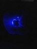
Baudouin Posted August 25, 2008 Author Share Posted August 25, 2008 Have just added some lights inside the apple logo in 3D. Not bad specially with the door covered up. Still have to organize the 5 blue lights correctly. Pics follow... The pictures are here : Edit : there are seven leds now. Link to comment https://www.insanelymac.com/forum/topic/93600-my-nearly-finished-hack-the-tosh/page/3/#findComment-868921 Share on other sites More sharing options...
Baudouin Posted August 30, 2008 Author Share Posted August 30, 2008 After a lot of search, I finally found and bought two from ebay. can't wait to try them. sata power and data backplate . For those who have no black Apple connectors. Edit 09/09/08 : small probl. There are male connectors. Have found female connectors, well hope there are, will see upon arrival. Link to comment https://www.insanelymac.com/forum/topic/93600-my-nearly-finished-hack-the-tosh/page/3/#findComment-873750 Share on other sites More sharing options...
Baudouin Posted September 9, 2008 Author Share Posted September 9, 2008 I have not yet connect the G5 Laing pump. But have found this picture . You can see that the external is black (neutral) and the second beside is yellow thus 12 V . I guess the third has to be RPM and the fourth or 12V or black. I would test first just the two external wires; black and yellow and if nothing happens then the fourth with 12 V and if necessary with black. If someone has already done this, lease report it . I will give a try tomorrow. First prepare some wires to connect the pump to a molex plug. Link to comment https://www.insanelymac.com/forum/topic/93600-my-nearly-finished-hack-the-tosh/page/3/#findComment-885010 Share on other sites More sharing options...
Baudouin Posted September 11, 2008 Author Share Posted September 11, 2008 Have connected the fourth (black) and third yellow 12V) wires. It works because the pump become warm but I heard no noise. Is this pump so still ? Have to connect to the liquid circuit to see if it is actually working. Link to comment https://www.insanelymac.com/forum/topic/93600-my-nearly-finished-hack-the-tosh/page/3/#findComment-887294 Share on other sites More sharing options...
Baudouin Posted September 17, 2008 Author Share Posted September 17, 2008 Concerning the Apple black plate for sata connections in the Mac Pro. Do not buy this or this because when they say female connectors, they are talking about the plug for the mobo, not the connections for the HDD's. But this is what could do the job : Link to comment https://www.insanelymac.com/forum/topic/93600-my-nearly-finished-hack-the-tosh/page/3/#findComment-895317 Share on other sites More sharing options...
Baudouin Posted September 26, 2008 Author Share Posted September 26, 2008 For those who are interessed in the Apple sata power connection : If you take a colored sata power cable, the yellow will be on the 90° side of the plug and then black, red, black. If you use a cable converter sata power plug to molex plug, you will see that the yellow cable is straight connected and the others are crossed because on the side of the molex, there are yellow, black, black, red. The Apple sata power is organised like a cable converter sata power plug to molex plug. So yellow, black, red, black on the Sata HDD side and yellow, black, black, red on the Mobo side. Top of pix, sata HDD side : yellow, black, red, black Bottom of the pix, 4 pins Mobo side : yellow, black, black, red The labelled wire is the yellow/12V. Link to comment https://www.insanelymac.com/forum/topic/93600-my-nearly-finished-hack-the-tosh/page/3/#findComment-907636 Share on other sites More sharing options...
fr3z3rburn Posted October 3, 2008 Share Posted October 3, 2008 if you want challenge stick a hackintosh with core2duo cpu into a g4 powermac cube, and make it all work. It's quite easily doable now because of this >>>>>> http://www.mini-box.com/Intel-DG45FC-Mini-ITX-Motherboard You may have to rearrange some things, but its quite possible. fr3z3rburn Link to comment https://www.insanelymac.com/forum/topic/93600-my-nearly-finished-hack-the-tosh/page/3/#findComment-916329 Share on other sites More sharing options...
Baudouin Posted October 3, 2008 Author Share Posted October 3, 2008 Thanks for the link and for reading the thread through. In fact some years ago, five or more, my sons were playing Counter Strike and the yongest bought a shuttle PC with his Lan Party prizes and I started to fantasize to rebuild a Cube inside the Shuttle case. I still have one working Cube and parts to complete two others. Now that the Intel Proc are used inside the Macs, I am thinking about a HackingCube. But finish this Hack first, lot of work to do...But I will later build a HackingCube. Link to comment https://www.insanelymac.com/forum/topic/93600-my-nearly-finished-hack-the-tosh/page/3/#findComment-916510 Share on other sites More sharing options...
teknojunkie Posted October 10, 2008 Share Posted October 10, 2008 For those who are interessed in the Apple sata power connection : If you take a colored sata power cable, the yellow will be on the 90° side of the plug and then black, red, black. \ If you use a cable converter sata power plug to molex plug, you will see that the yellow cable is straight connected and the others are crossed because on the side of the molex, there are yellow, black, black, red. \ The Apple sata power is organised like a cable converter sata power plug to molex plug. The labelled wire is the yellow-12V Oh Ok, So I think I know what you mean So A regular Sata Cable is Yellow. Black. Red. Black. And a Sata Cable to Molex would be Yellow. Black. Black. Red. And A Apple Sata would be the same as the molex converter Yellow. Black. Black. Red. Link to comment https://www.insanelymac.com/forum/topic/93600-my-nearly-finished-hack-the-tosh/page/3/#findComment-924661 Share on other sites More sharing options...
Baudouin Posted October 10, 2008 Author Share Posted October 10, 2008 You nearly got it amantheboy : "Oh Ok, So I think I know what you mean So A regular Sata Cable is Yellow. Black. Red. Black." At the Sata side "And a Sata Cable to Molex would be Yellow. Black. Black. Red." At the Molex side "And A Apple Sata would be the same as the molex converter Yellow. Black. Black. Red." At the 4 pins Mobo side and Yellow. Black. Red. Black at the Sata side I will upload another pix with the wires close from each other so it easier to see the difference. Edit : here is the pix : As you see, it does not matter Apple or Original Sata or mod Sata cable, the connections should be always : Yellow, Black, Black, Red on the molex side and Yellow, Black, Red, Black on the Sata side. I edit the previous pix : The Apple sata power is organised like a cable converter sata power plug to molex plug. So yellow, black, red, black on the Sata HDD side and yellow, black, black, red on the Mobo plug side. Top of pix, sata HDD side : yellow, black, red, black Bottom of the pix, 4 pins Mobo side : yellow, black, black, red The labelled wire is the yellow/12V. Link to comment https://www.insanelymac.com/forum/topic/93600-my-nearly-finished-hack-the-tosh/page/3/#findComment-924801 Share on other sites More sharing options...
teknojunkie Posted October 12, 2008 Share Posted October 12, 2008 k got it! thank you diagram soon. Link to comment https://www.insanelymac.com/forum/topic/93600-my-nearly-finished-hack-the-tosh/page/3/#findComment-927044 Share on other sites More sharing options...
Baudouin Posted October 12, 2008 Author Share Posted October 12, 2008 k got it! thank you diagram soon. OKidiki . Thanks a lot. Link to comment https://www.insanelymac.com/forum/topic/93600-my-nearly-finished-hack-the-tosh/page/3/#findComment-927730 Share on other sites More sharing options...
Baudouin Posted December 13, 2008 Author Share Posted December 13, 2008 the only thing i dont like is how the G4 door(obv) doesnt cover the entire opening. leaving the top shelf and the corners visible. take the original G5 door. cut a hole in it the size of the G4 door. put them toogether. and make it motorize out. that. would be an amazing mod. I heard you HacOSXuser, I am cutting a hole inside the G5 door of the size of the Apple logo and will insert a piece of acrylic panel, maybe coming a little bit on the outside as the G4 door was not flat but a little convexe; and the original door will be attached to the mobo plate, they will then move together. Link to comment https://www.insanelymac.com/forum/topic/93600-my-nearly-finished-hack-the-tosh/page/3/#findComment-997221 Share on other sites More sharing options...
tazevedo317 Posted December 14, 2008 Share Posted December 14, 2008 god that would look so good cant wait to see it but dont rush time will make it perfect. Link to comment https://www.insanelymac.com/forum/topic/93600-my-nearly-finished-hack-the-tosh/page/3/#findComment-997956 Share on other sites More sharing options...
Baudouin Posted December 14, 2008 Author Share Posted December 14, 2008 No worries, it will take what it takes but it will be done. In the meantime, some on going pix: From where we ended : we are going to here : just sprayed a chrome watercolored paint onto the acrylic panel view from the inside, showing the attached opening system frame : and to here : 3 days to draw the apple logo onto the original G5 door, first centered with the apple on the door and then with the 3 D apple inside : because this one is in the middle of the mobo tray : Cutting has started, already used three blades, have to buy some more on monday... Link to comment https://www.insanelymac.com/forum/topic/93600-my-nearly-finished-hack-the-tosh/page/3/#findComment-998797 Share on other sites More sharing options...
Baudouin Posted December 22, 2008 Author Share Posted December 22, 2008 Bought a set of ten blades. Half way on the cutting. Hope to finish for Christmas with the apple logo in acrylic panel cut . Hope to install the acrylic in the door hole before next year. Link to comment https://www.insanelymac.com/forum/topic/93600-my-nearly-finished-hack-the-tosh/page/3/#findComment-1010505 Share on other sites More sharing options...
Recommended Posts