MiniHack Posted April 23, 2013 Author Share Posted April 23, 2013 Very nice! Although I've always thought the idea of having the reservoir, pipes or radiator external to the case was ungainly I NEED a laser cutter now. I am aiming to make this design to be a little less ungainly! And as far as getting your own cutter goes - go for it. BUT be VERY prepared for fires, heart ache, and wallet ache along the way. Link to comment https://www.insanelymac.com/forum/topic/287441-minihack-a-slightly-different-g5-case-mod/page/3/#findComment-1909912 Share on other sites More sharing options...
nickjf20 Posted April 23, 2013 Share Posted April 23, 2013 Maybe I'll just stick to ordering from you for the time being Talking of that ... I've got another project I'd like to run by you - I'll message you Link to comment https://www.insanelymac.com/forum/topic/287441-minihack-a-slightly-different-g5-case-mod/page/3/#findComment-1909967 Share on other sites More sharing options...
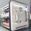
MiniHack Posted April 27, 2013 Author Share Posted April 27, 2013 A bit of an update today. After lots of measuring with bits of card and paper I have made up the first try at a full width motherboard tray for this. The tray is cut from 5mm black acrylic (too shiney I think!) and is to be positioned for cable and (potentially) tube management. I went full width but not full height as I need to get the PSU case in and out easily and want that to be able to be done without moving the motherboard. So, this is me putting in the fixings to hold the tray: I used rivnuts (of course!) to go through the existing inner case holes. Unfortunately on their own they did not give me quite enough room for cable management behind the tray and then with these standoffs attached (5mm) the tray interfered with what I wanted to do with the front IO. So instead of cutting another hole in the tray (which I think would have caused a weak point) I swapped the 5mm spacers for a 2mm nut fixing. Not ideal, but it would give me about 6 or 7mm of cable management area behind the tray. Needless to say in working out all of this my tray was removed, and re-fitted what seemed to be a dozen times. Here is now a front view with tray and a mobo fitted for size. The mobo itself is raised 22mm above the tray and gives plenty of room if I should ever decide to use the area under there for running watercooling pipes. I was initially a little surprised by how tall it was from the tray but that is just a consequence of building in those 12mm holes between IO shield bottom and where the backplate meets the case edge. There will be no big air coolers in this G5 and it has to be water all the way!!!! After fitting the mobo in position it was time to look again at how the PSU case will work. I drew onto the case top the best positions for the ATX to emerge and the CPU power connection and then cut slots in the top so they can come out of the case and run into the correct positions with as little cable protruding as possible. Then it was on to do a bit more cable routing to work out the management. The SATA cables go to the right area, but I want to find some right angled cables that will stack on top of each other - anyone know where I can find some?? - then I can make a closure to cover up most of the cable hole here. The enclosure variant I'll be using now is this one: I like the matt black sides and think it will fit the build interior nicely. Here it is trial fitted. When it is finally in position it'll sit on the custom PSU cover plate and be screwed in to the power supply left hand top screw. It will also be fixed to the mobo tray by some spacers to both keep it steady but also add strength to the tray itself. There is quite a lot of room to the right of the hotswapper and in fact it could be used for two more fans - or maybe to internally mount a reservoir if I ever get the cash and hardware desire to move from the Kraken x60. Finally, here are some more views of the front IO as it is now. ] I worked out the fixing to the tray and also to the internal standoffs so that brings a potential kit a bit closer. However, the decision to keep the front switch and LED combo is not necessarily a great one. While the intention is to allow a flush mounting option that looks a little more original than some, the soldering of the tiny switch PCB is a PITA. When doing that part of the mod I lifted the trace to the + side of the LED and then had to wire the + of the LED direct to the front side of the board. It was stupid of me, but one small slip can easily trash this little PCB. The pic above shows the front IO as work in progress. It will be JB'd in place from behind and then it could be given the front flush plate treatment, but for my own industrial look for this mod I will probably stick with this: So it is coming along. Decisions at the moment are that in the absence of any sponsor for using their water cooling gear in my case it will keep the Kraken X60, I also will not be putting a "door" behind the mobo tray and prefer the idea of a clean side to it. Once the cabling is in place there won't be much reason to open up that side and in any event with the new panel design it will only be a few screws to undo to get to it. I will though be sticking with my "door in a door" ideas for the opening side. 1 Link to comment https://www.insanelymac.com/forum/topic/287441-minihack-a-slightly-different-g5-case-mod/page/3/#findComment-1910836 Share on other sites More sharing options...
Baudouin Posted April 27, 2013 Share Posted April 27, 2013 Very interesting to be confront with others'ideas. Great and nice job. 1 Link to comment https://www.insanelymac.com/forum/topic/287441-minihack-a-slightly-different-g5-case-mod/page/3/#findComment-1910913 Share on other sites More sharing options...
Mr.D. Posted April 27, 2013 Share Posted April 27, 2013 Then it was on to do a bit more cable routing to work out the management. The SATA cables go to the right area, but I want to find some right angled cables that will stack on top of each other - anyone know where I can find some?? - then I can make a closure to cover up most of the cable hole here. My suggestion would be a right angle and a 'left' angle plug - the 'left' being a 270 rather than 90 turn. The right angle going down, the left angle going up, then fold the cable back on itself. Assuming you have a pliable enough cable (monoprice has some good Sata3 and 6 cables that aren't super thick and are pretty cheap) you'll just have a small bump going up. To use the stock G5 HDD mounting I had to use one left and one right angle cable because one went up and the other went down. Only took me 5 different combinations to get that all correct! Two questions: 1> Was it required to cut the TeslaConverter case to get the cables out because of the MB height? I think you did a good job of cutting very little, but now you have a raw metal edge rather than the folded metal edge that was there originally - Not as pretty (that's minor) and a potential area to catch and/or cut the sheathing or the cables inside (that's major). 2> Are you sticking with black plastic parts for your final build or are these just templates for metal pieces to come later? Overall looking very sharp and progressing nicely. PS - I got my NixieTube fan controller in - now I just have to figure out a way to use it w/o modifying my case - it can be done!! 1 Link to comment https://www.insanelymac.com/forum/topic/287441-minihack-a-slightly-different-g5-case-mod/page/3/#findComment-1910914 Share on other sites More sharing options...
MiniHack Posted April 28, 2013 Author Share Posted April 28, 2013 My suggestion would be a right angle and a 'left' angle plug - the 'left' being a 270 rather than 90 turn. The right angle going down, the left angle going up, then fold the cable back on itself. Assuming you have a pliable enough cable (monoprice has some good Sata3 and 6 cables that aren't super thick and are pretty cheap) you'll just have a small bump going up. To use the stock G5 HDD mounting I had to use one left and one right angle cable because one went up and the other went down. Only took me 5 different combinations to get that all correct! Two questions: 1> Was it required to cut the TeslaConverter case to get the cables out because of the MB height? I think you did a good job of cutting very little, but now you have a raw metal edge rather than the folded metal edge that was there originally - Not as pretty (that's minor) and a potential area to catch and/or cut the sheathing or the cables inside (that's major). 2> Are you sticking with black plastic parts for your final build or are these just templates for metal pieces to come later? Overall looking very sharp and progressing nicely. PS - I got my NixieTube fan controller in - now I just have to figure out a way to use it w/o modifying my case - it can be done!! On the SATA cable thing that's a good idea. Thanks. I am surprised though that with all the low profile dual SATA sideways outlets on the mobos on the market t is so hard/impossible to find someone making SATA cables that work well together for cable management. Seems a pretty obvious thing to do. On the Tesla case I really needed to cut it to work well for a minimum cable run. I filed the edge to make as smooth as I could and the cover plate I'll make will pinch the cable with a plastic edge so that when it is on the braiding won't come in to contact with the metal edge underneath. With the black panels at the moment I am not thinking of them being the final finished look, but I wanted to be using something that at least looks nice (to me!) so I can better think about what I might like in the end (does that make sense??). What I mean is I could have saved a few pennies by doing everything in transparent acrylic right now but looking at the case while I am working would not be pleasant!! Also I am still playing around with different fasteners and everything just to see how different options might look. Truth be told I still haven't decided how I want the final finish to be. I do like the black and silver look and it may stay. I might see how much it'd cost me to replicate the look with aluminium panels instead of plexi. I might go for some polished aluminium (in which case I may have to strip the Lamptron and polish the front plate. I might go black and white. I might take the hard route and make all the exterior parts flush and then go for a more stock colour. Happy to take suggestions...... I do love the Nixie display. Where are you thinking of putting yours? If there is space behind the front mesh somewhere it'd be cool to have the tubes glowing through it? The radio remote gives a lot of placement options. It is a bit of an expensive toy, but soooooo cool. By the way where did you buy yours from? 1 Link to comment https://www.insanelymac.com/forum/topic/287441-minihack-a-slightly-different-g5-case-mod/page/3/#findComment-1910974 Share on other sites More sharing options...
Mr.D. Posted April 28, 2013 Share Posted April 28, 2013 yup - putting it on top of the teslaconverter case up front behind the mesh. The only issue now is how to encase it - that is kicking my ass at the moment. and I bought mine from the same place you bought yours - nobody in the US had it in stock, and most places had no eta. I just bit the bullet and bought it from Scotland. Black and silver pretty much always go together - and it works well on yours. If you did do it in aluminum, then the problem would be how to match the existing aluminum... Link to comment https://www.insanelymac.com/forum/topic/287441-minihack-a-slightly-different-g5-case-mod/page/3/#findComment-1911031 Share on other sites More sharing options...
nickjf20 Posted May 2, 2013 Share Posted May 2, 2013 Can't say I'm a fan of the front panel, but I really like the honeycomb pattern you've got on the motherboard tray! 1 Link to comment https://www.insanelymac.com/forum/topic/287441-minihack-a-slightly-different-g5-case-mod/page/3/#findComment-1912141 Share on other sites More sharing options...
Recommended Posts